DWG-013 · MECHANICAL DESKWARE · RISD 2025
Rotational Phone Stand
A mechanism study in which rough models, printed gears, and a final assembly explore one-handed angle adjustment.
FIG 01 · IN USE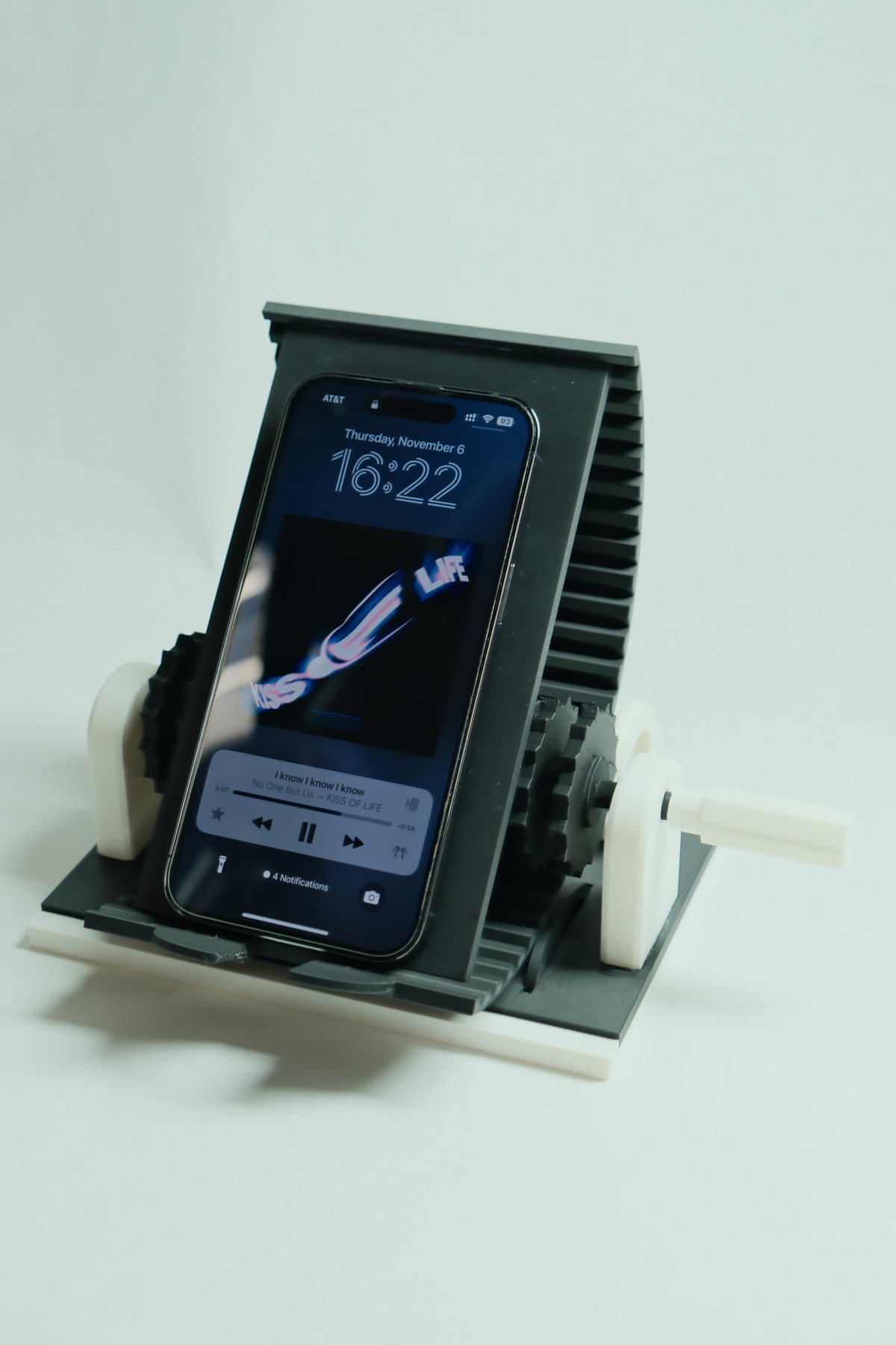
SEC 01
Brief概要
ANGLE CHANGE AS A PHYSICAL INTERACTION
How can a phone stand make frequent repositioning stable, legible, and satisfying with one hand?
For video calls and everyday desk use, the side grip gives angle adjustment a dedicated point of control. Rough assemblies explored the support and grip arrangement; printed components brought the toothed interface into a complete stand. The design keeps the moving parts visible so the hand input and platform response can be read together.
COURSEID DESIGN PRINCIPLE
FOCUSMECHANISM · INTERACTION
TOOLSSKETCH · SOLIDWORKS
PROCESS3D PRINT · ITERATE
SEC 02
Rotation by Hand手动调节
FIG 02 · MOTION STUDY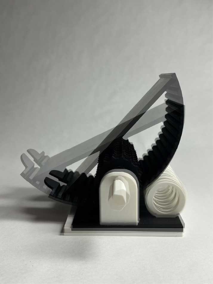
INPUT AND OUTPUT STAY VISIBLE
The side grip gives the adjustment a clear point of control while the toothed edge makes each change readable.
The platform, support body, and rotating interface were developed as one assembly rather than separate styling parts. The layered side study records how the phone surface moves while the base remains planted.
INPUTONE-HANDED TURN
TRANSFERTOOTHED INTERFACE
OUTPUTADJUSTABLE PLATFORM
SEC 03
Mechanism Language机构语言
MECHANICS BECOME THE AESTHETIC
Repeated teeth, exposed wheels, and a ringed grip make the adjustment system the product’s visual identity.
The loose blue gear and toothed strip isolate how the teeth meet. The assembled details show the same question in context: how the side control, moving platform, and fixed support fit together. Repeated teeth and exposed wheels then give the stand its visual character.
FIG 03 · CRANK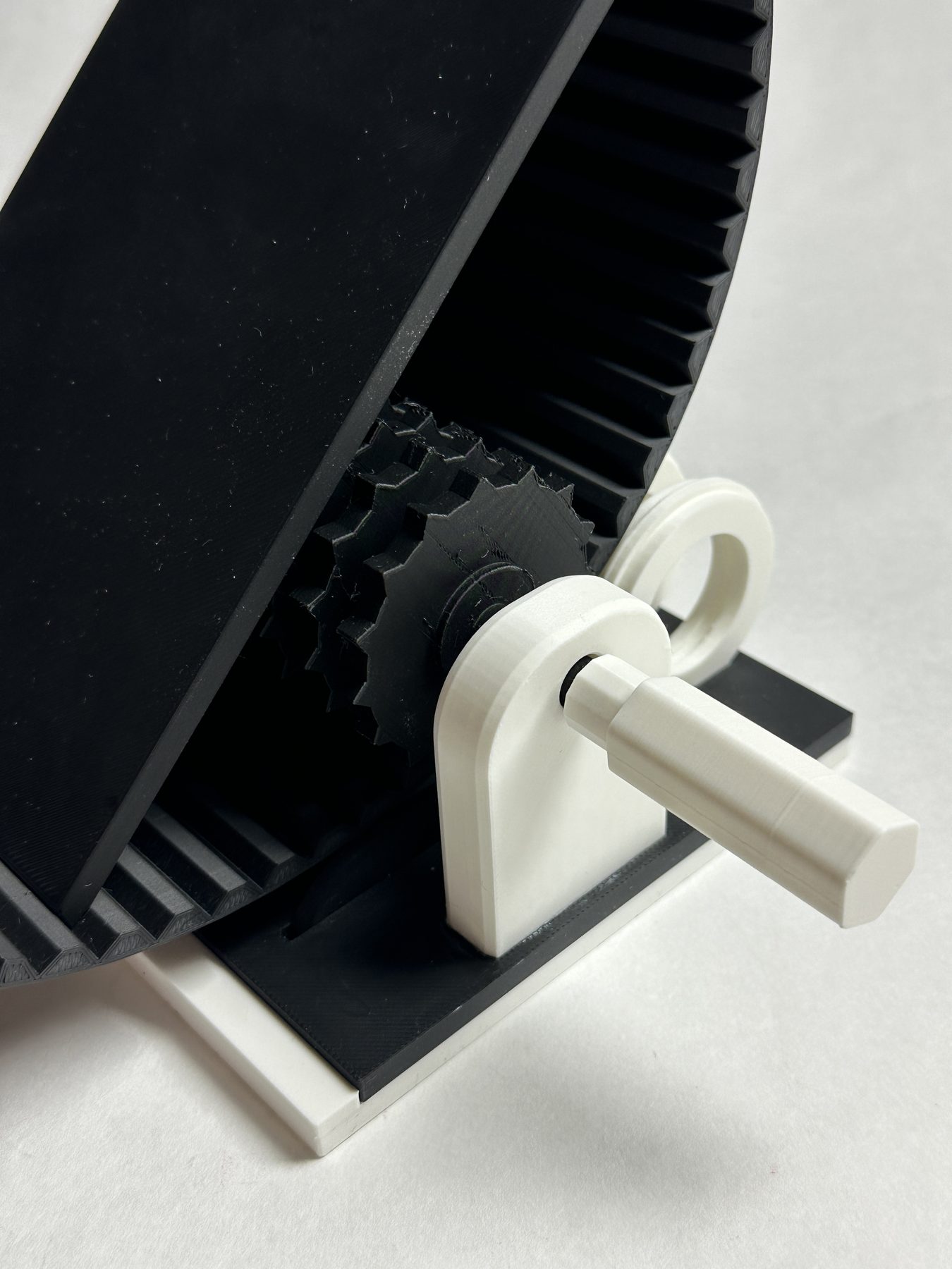
FIG 04 · INTERFACE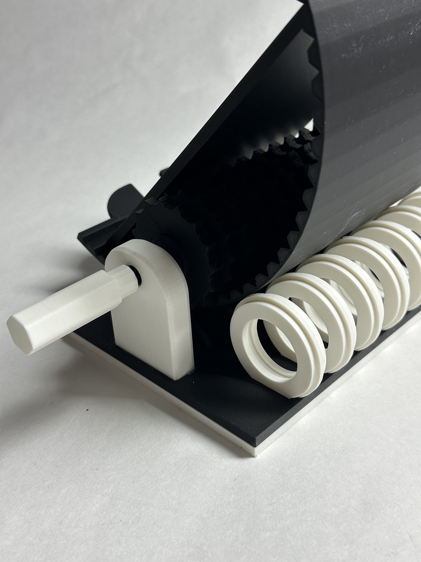
FIG 05 · GEAR STUDY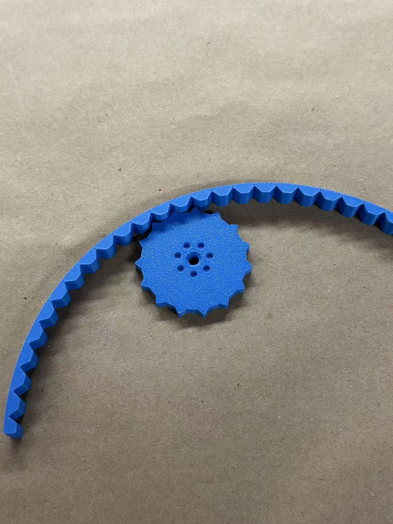
SEC 04
From Sketch to Fit从草图到配合
THE FORM FOLLOWED THE ADJUSTMENT
Each model makes a different design question visible: movement, support, transmission, or assembly.
The sketch explores angle and rotation options. Two rough assemblies compare platform proportions, support geometry, and side-control arrangements; the exposed cardboard mechanism makes the toothed contact accessible. Peer feedback and repeated prints informed the fit, while the SolidWorks model brought the components together before the final black-and-white assembly.
FIG 06 · CONCEPT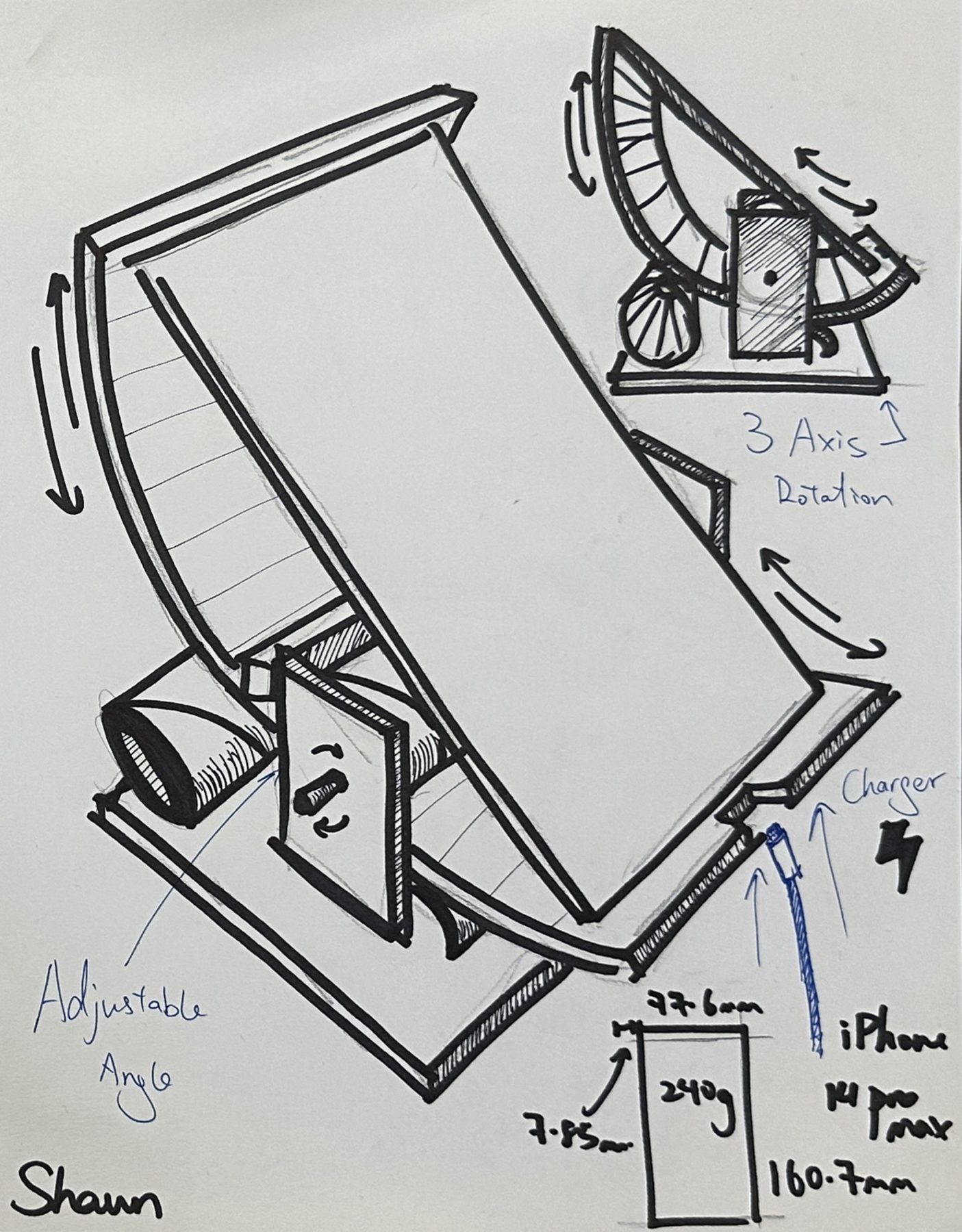
FIG 07 · ITERATIONS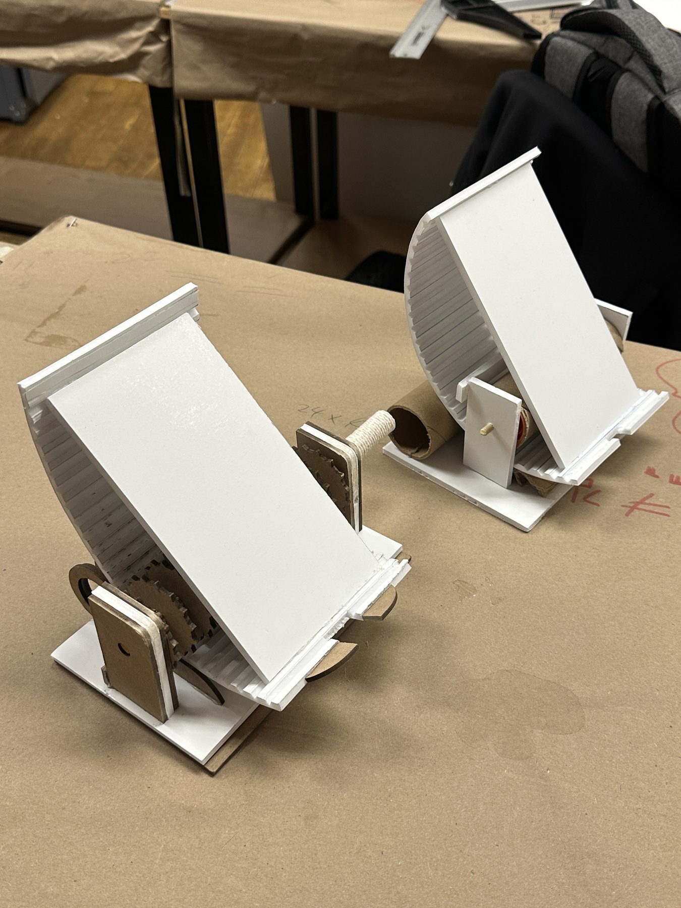
FIG 08 · PROTOTYPE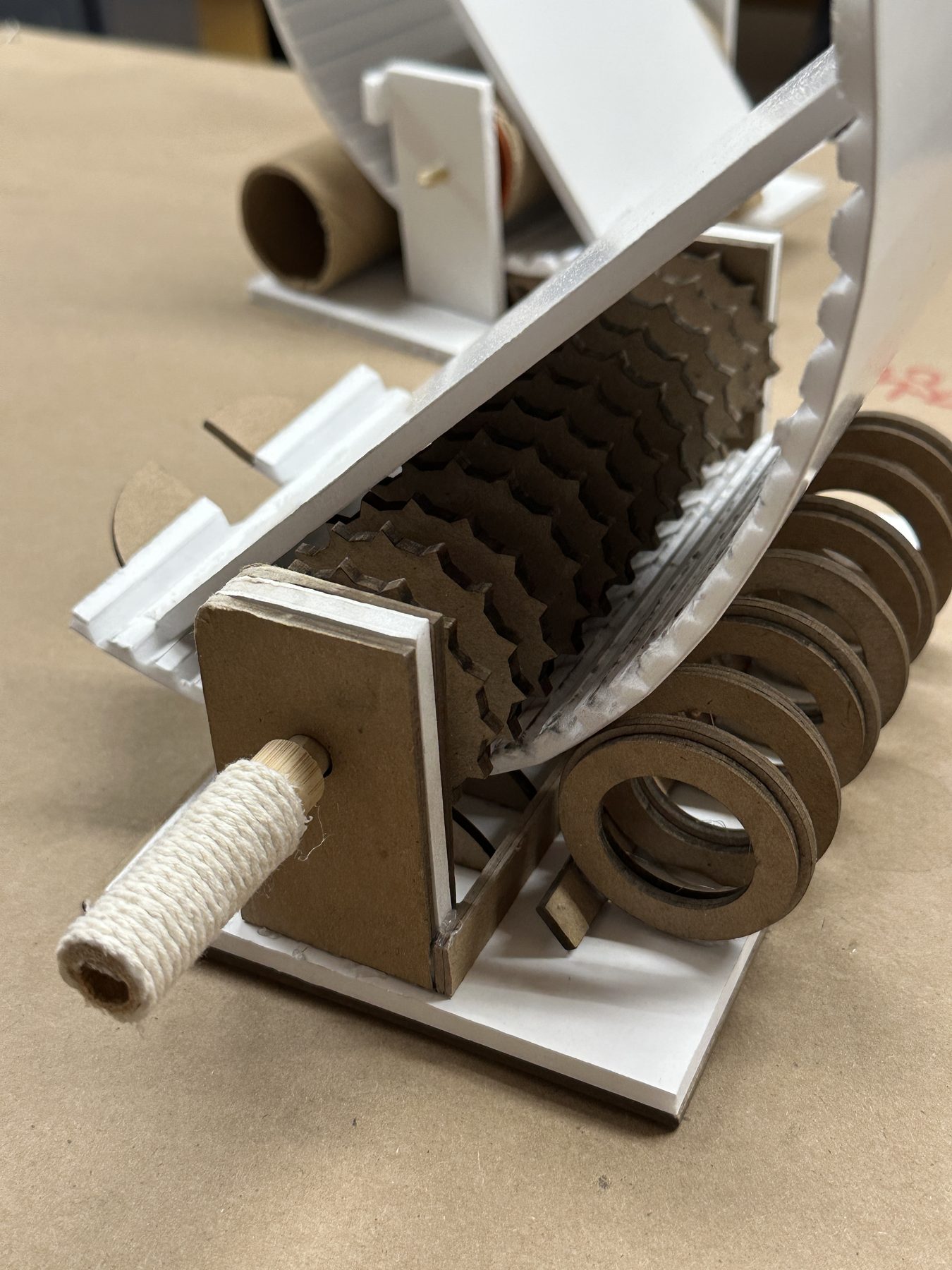
FIG 09 · CAD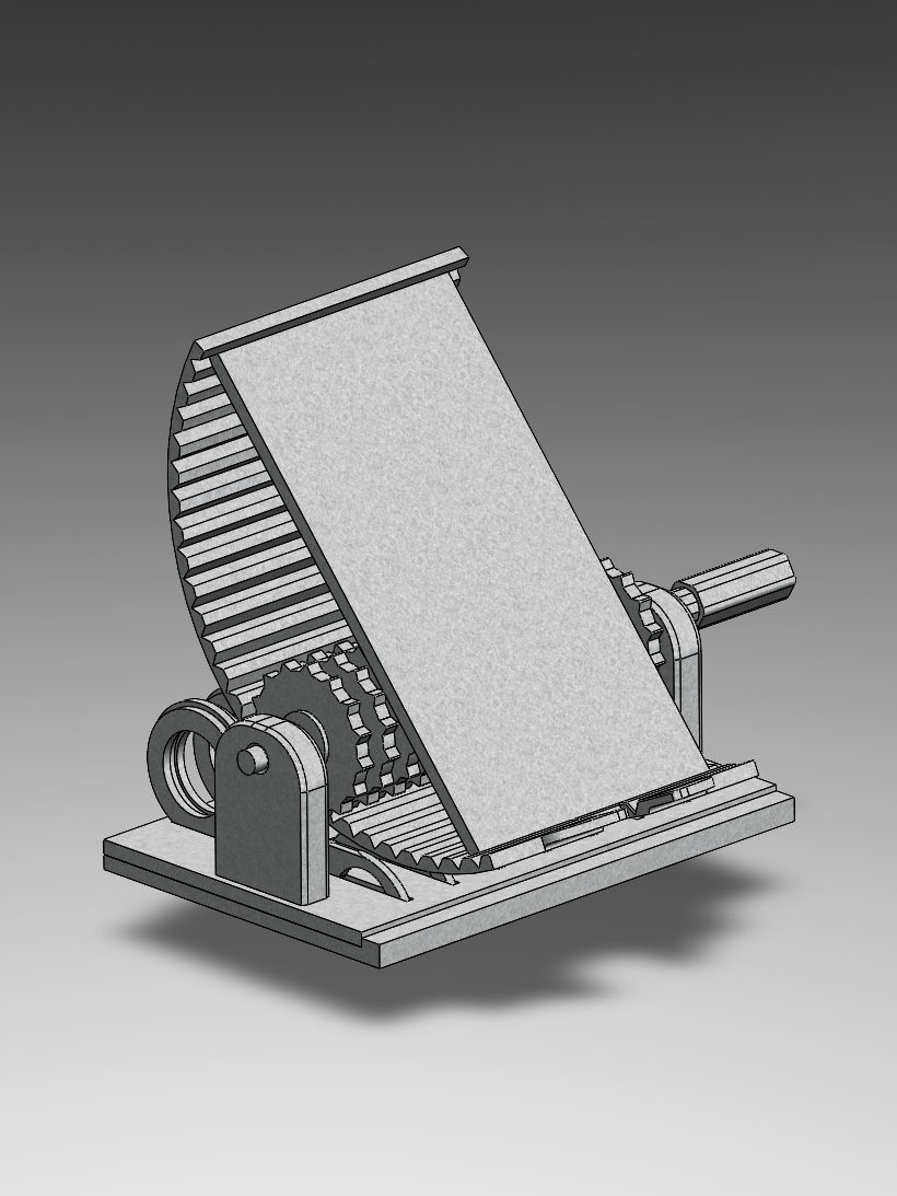
SEC 05
Final State最终状态
FIG 10 · FINAL OBJECT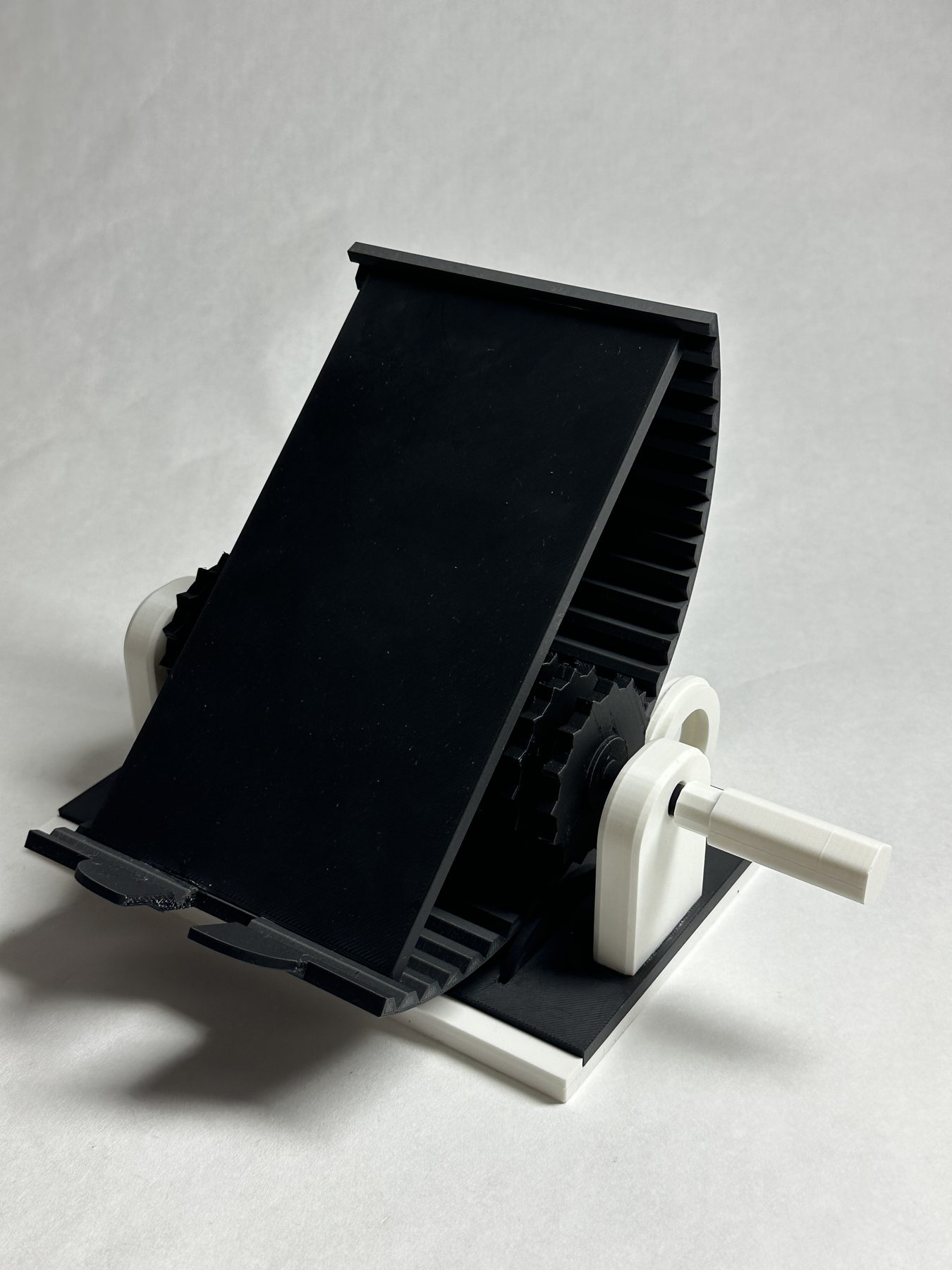
A MECHANICAL DESK OBJECT
The resolved prototype keeps every adjustment component visible and reachable.
The final contrast between black structure and white controls clarifies what stays fixed, what moves, and where the hand engages—turning the mechanism into both interface and character.